Aviator
Predictor apk
Aviator Predictor is a mobile application for Android based on artificial intelligence. At the heart of the application, we combined the mathematical model from ChatGPT 4 and the statistics of the Aviator game. For more than a year, we have analyzed and continue to analyze the statistics of each casino site.
Download apk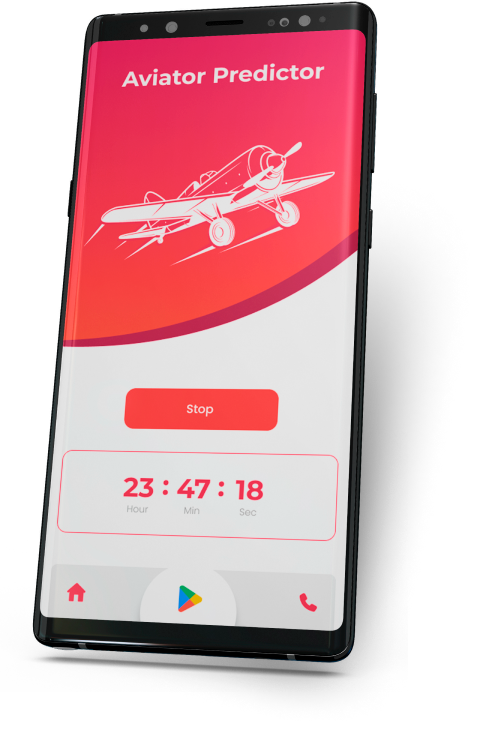
Download
Aviator Predictor
How do we collect statistics? Every day, several dozen servers parse and record data from each round. We upload this data via API to ChatGPT to analyze and train our Aviator Predictor application. Over the past 6 months, our results have gotten significantly better. When we first created the Aviator Predictor app, the accuracy was very low at no more than 46% vs. 98% now: in the new version of the Aviator Predictor v2.5.1 app.
Predictor
Aviator
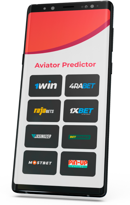
Why is it important to register at the specified casino? As you know, each casino has very different airplane rounds. It is in the specified casinos that we have collected at least a year's worth of rounds statistics and analyzed them with the help of artificial intelligence. This approach allowed us to predict with 98% accuracy the result of each next round in the Aviator Predictor application.
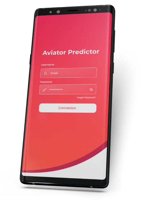
Predictor login password
As you know, computational methods of generating pseudo-random numbers do not achieve the goal of true randomness when generating data for each next round in the game Aviator. That's why the program developers add the data of the first and last bet made. This is why we have added a mathematical model from ChatGPT-4 to our Aviator Predictor application. Artificial intelligence trained on annual statistics are good at this task.
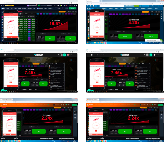
Examples of app usage
Take a close look at the examples below. You can see how accurately Aviator Predictor works with the selected casino sites. In the new version, there is no need to press a button to get new data and the result of the next round appears automatically.
Only on the official website of Aviator Predictor app you can get Login and Password to enter the app. Important: We do not sell the application, you can download it absolutely free of charge.
Download the app
Download the apk file of Aviator Predictor app quickly and absolutely free of charge.
Download APPSign up and download the Aviator Predictor app from the official website.